Lighting control / Scintillax journal
Lighting control modules for LED, explained.
How the relay and dimming modules in a lighting control panel work with LED drivers: phase dimming, 0–10V, DALI and DMX, inrush, minimum levels and the panel schedule.
A smart lighting control panel is only as good as the modules on its rails. Each module switches or dims one or more lighting zones, and each zone ends in an LED driver that expects a particular kind of control. Choose the right pairing and the light rises smoothly, holds a quiet low level and turns off cleanly. Choose the wrong one and you may see flicker, hear a hum or watch the lights drop out before the slider reaches the bottom.
This guide explains the common module types in residential lighting control panels and the questions to ask before fixtures are ordered.
What a module does
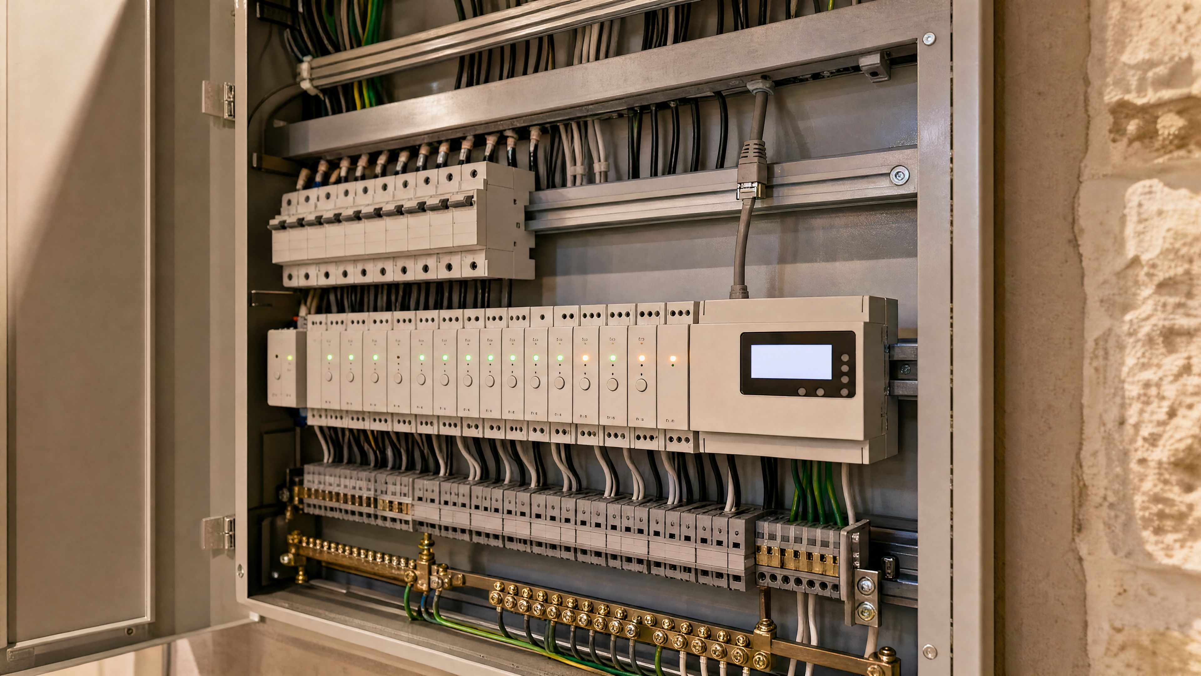
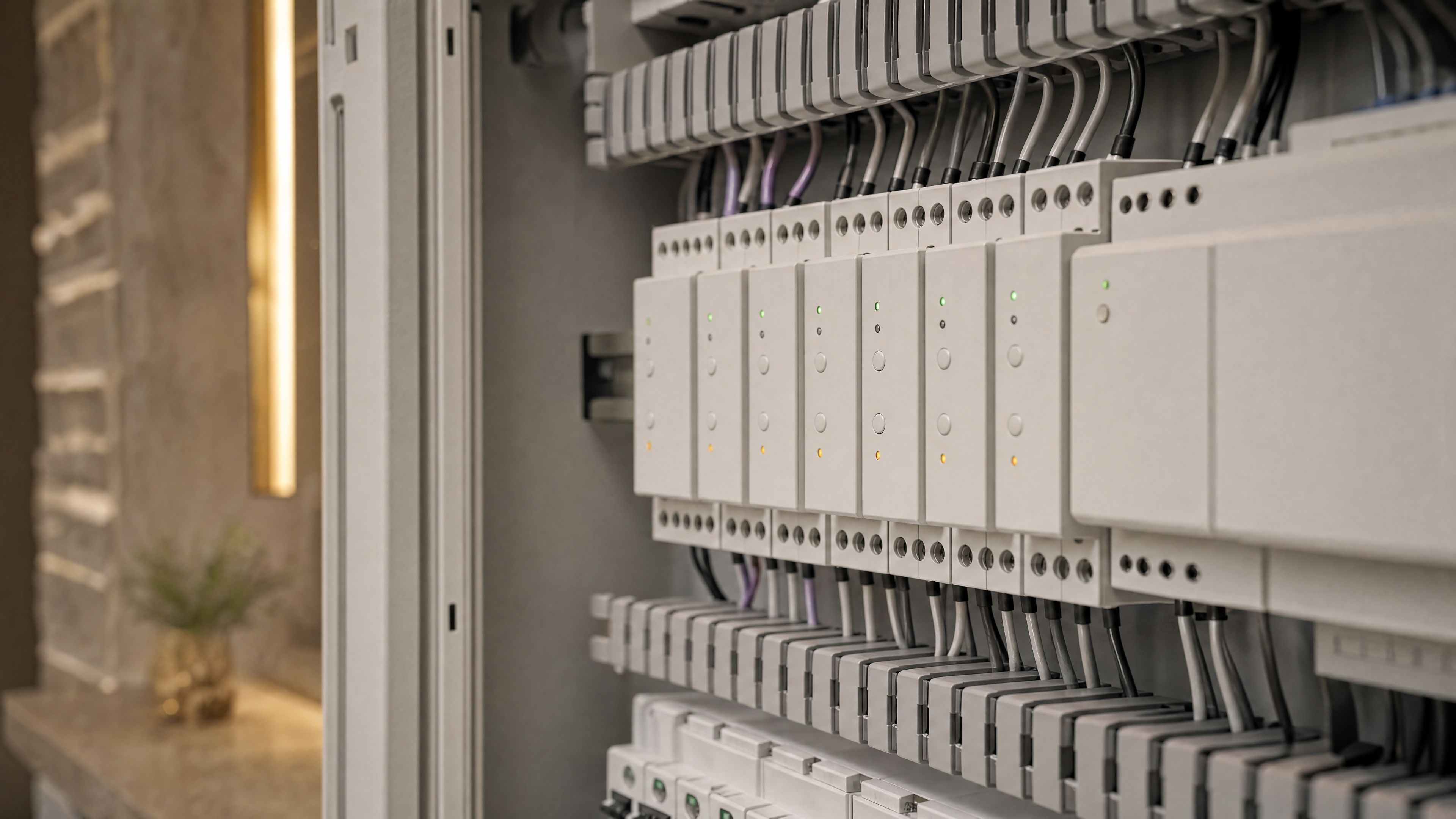
A module sits on a DIN rail in the panel, receives instructions from the controller and acts on the zones wired to it. Most modules have several channels, so one module can serve several zones. There are two broad families:
- Relay modules switch power on and off.
- Dimming modules set a level, either by shaping the power to the fixture or by sending a separate control signal to its driver.
Many panels combine both. A landscape zone may need only a relay, while a cove and pendants need dimming. Professional platforms offer families of modules for this reason. Lutron’s HomeWorks system architecture, for example, lists DIN-rail modules for phase dimming, switching, 0–10V, DALI and DMX within one system.
Relay modules and LED inrush
A relay is the simplest module: on or off. It suits non-dimmable loads, exhaust fans and lighting that only switches, as well as the power side of fixtures dimmed by a separate signal.
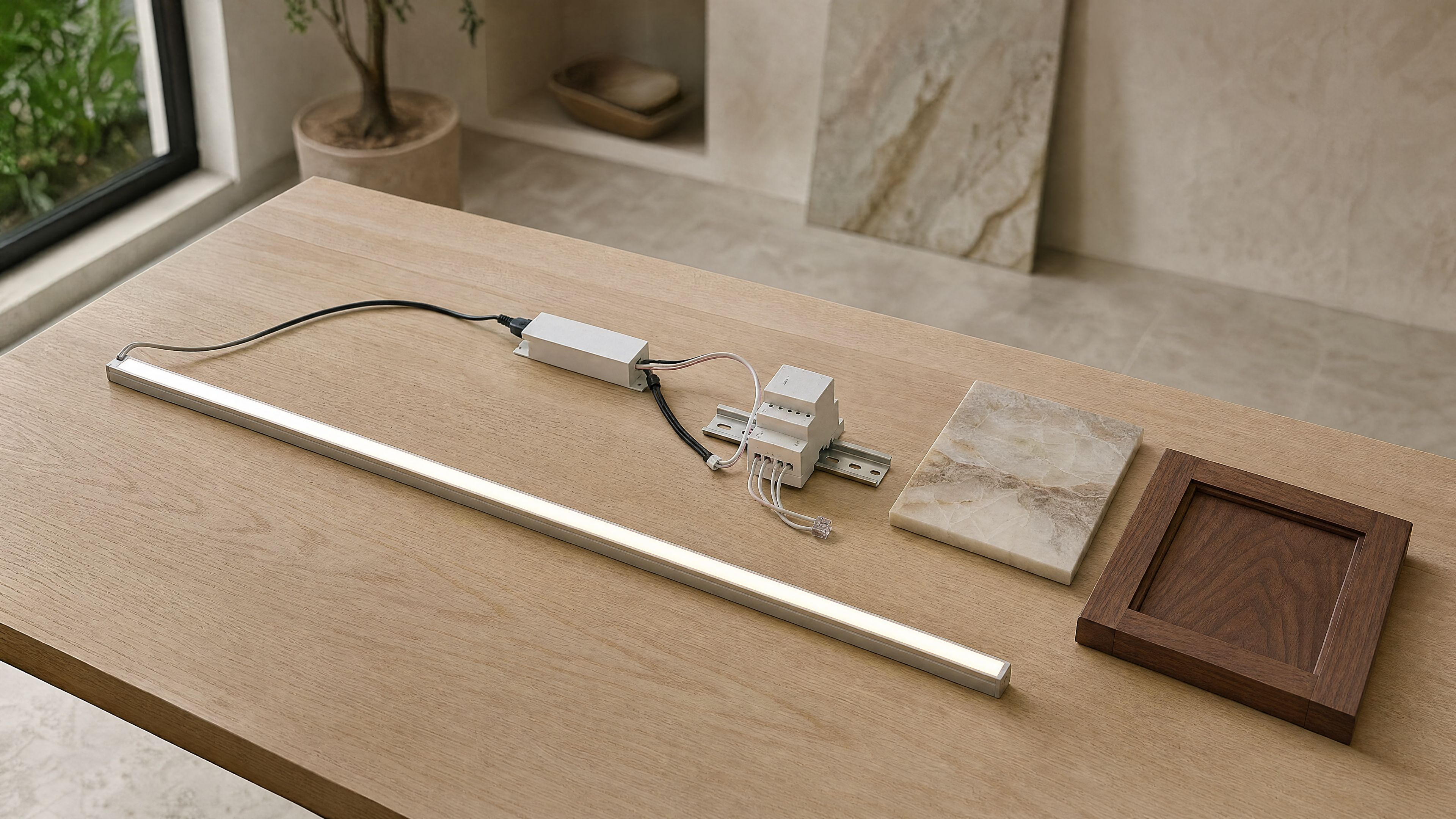
LED drivers draw a brief surge of current when they switch on, called inrush. It lasts a few milliseconds but can be many times the running current, and a group of drivers on one relay adds up. Relays are therefore rated for LED or capacitive loads separately from their ordinary current rating. Check the driver’s inrush figure against the relay’s LED rating, and split large groups across channels where needed.
Phase dimming: forward and reverse
Phase dimming controls the light through the same two wires that power it, by trimming part of each wave of the alternating current.
- Forward phase, also called leading-edge, cuts the beginning of each half-wave. It is common for magnetic transformers and many retrofit lamps.
- Reverse phase, also called trailing-edge or electronic low voltage, cuts the end of each half-wave. Many integral LED fixtures and electronic drivers dim more smoothly this way.
The driver’s data sheet states which method it supports. Leviton’s forward and reverse phase application note observes that LEDs generally perform better with reverse phase, though the driver’s own requirement comes first. Some modules can be set either way per channel: Control4’s 8-channel adaptive phase dimmer can switch, use forward or reverse phase or detect the load, and lists its own LED limit per channel. Phase dimming needs no extra control wiring, which makes it convenient where cables already exist.
0–10V dimming
With 0–10V control, the driver receives full power and a separate pair of low-voltage wires carries the dimming signal: 10 volts for full output, lower voltages for lower levels. A relay switches the power off when the zone goes dark, unless the driver supports dimming to off.
0–10V is common for linear LED, commercial-grade downlights and many LED tape drivers. Plan the extra conductors to every driver location, and confirm the low end of the range, because some drivers stop at a minimum level rather than fading fully to darkness. A standard exists, ANSI C137.1, but drivers do not all follow it equally; a national laboratory study found several tested drivers outside the standard. Testing the actual pairing matters.
DALI: an address for every driver
DALI, the Digital Addressable Lighting Interface, is an international standard published as IEC 62386. A two-wire bus links the drivers, and each driver receives its own address, so fixtures can be regrouped in software without rewiring. A single DALI line supports up to 64 control gear addresses, and DALI-2 adds certification for interoperability. The DALI Alliance’s quick start guide is a clear introduction.
DALI suits homes with many individually controllable fixtures, tunable-white lighting and projects that expect the layout to change. It asks for careful addressing and documentation at commissioning.
DMX for color and effects
DMX512, standardized as ANSI E1.11, comes from stage lighting. It carries up to 512 channels on one cable and is the usual choice for RGB, RGBW and pixel tape, where each color needs its own channel. A DMX decoder near the tape translates the signal for the LED. In a home, DMX is typically reserved for color features: a pool surround, a bar, a façade detail or a backlit onyx panel that changes tone.
Wired buses and wireless protocols
Modules also need a way to hear the controller and keypads. Professional platforms often use a wired bus between panel and keypads. KNX is an open standard with its own bus cable and DIN-rail switching and dimming actuators. Proprietary systems use their own buses or radio links, such as Lutron’s Clear Connect. Consumer ecosystems rely on Zigbee, Z-Wave, Wi-Fi or Thread with Matter.
The protocol affects which keypads, sensors and apps can join the system later. Prefer wired links for the panel and fixed keypads, and use wireless devices where cables cannot reach.
Read the driver data sheet
Before a fixture is approved, find these lines on its driver data sheet:
- Dimming method: forward phase, reverse phase, 0–10V, DALI or DMX.
- Dimming range: the lowest stable level, often stated as a percentage.
- Load limits: minimum and maximum load per channel.
- Inrush current: the peak current at switch-on.
- Compatibility: tested control products, if the manufacturer lists them.
- Flicker information: where published, especially at low levels.
A dimmable label on its own does not establish compatibility with a particular module. Test the selected fixture, driver and module together, at the lowest setting you intend to use.
Build a panel schedule
The panel schedule turns these decisions into a document you can keep. For each zone it lists the room, fixtures, load, driver type and location, dimming method, module and channel, breaker, keypad buttons and scenes. It guides the installation, supports the programming and makes later service far simpler.
Scintillax prepares the zone schedule together with the LED lighting design, so linear profiles, cabinet lights, backlit stone and landscape fixtures arrive with drivers the panel can control well. For the wider decision between panel and wall dimmers, read centralized lighting control or smart switches.
Bring your location, room photographs and the details that matter most. We can review the materials, light and practical requirements together.
Plan your lighting controlMaterial studies
The details that make the room.